
close
Choose Your Site
Global
Social Media


Views: 0 Author: Site Editor Publish Time: 2026-08-04 Origin: Site


Fluid connections dictate overall facility performance. Mismatched couplings lead directly to parasitic pressure drops. They also cause hazardous fluid leaks and accelerated component wear. These physical issues severely impact overall system efficiency over time. Navigating North American pneumatic and fluid power standards is a major core challenge. You must ensure precise alignment of thread geometries. You also need exact profile interchangeability and proper internal valve configurations. Ignoring these technical factors compromises safety and wastes energy.
Our guide provides a verifiable, specification-driven framework. We help you evaluate, shortlist, and implement correct components accurately. You will learn to optimize systems across industrial, hydraulic, and mold-cooling applications. By standardizing your connections, you eliminate frustrating operational bottlenecks. Read on to master thread standards, flow dynamics, and material selection principles.
Thread geometry dictates sealing reliability; standardizing on NPT configurations prevents the high-risk practice of cross-threading with incompatible international standards.
Flow type selection (open vs. valved) directly determines the system's pressure drop (Cv value) and acceptable fluid spillage during disconnection.
Application-specific profiles, such as the DME standard for injection molding, require exact plug-to-coupler matching to ensure safe operation under thermal and dynamic stress.
Material selection must align with system media; while brass offers excellent corrosion resistance for water and air, high-pressure hydraulics demand hardened steel.
Using an incorrect American standard quick coupling creates severe systemic risks. Incorrect profile matching causes immediate mechanical vulnerabilities in any fluid network. For example, mating an Automotive profile plug with an Industrial Interchange coupler might initially seem to fit. However, this pairing causes constant micro-leaks. It thoroughly compromises seal integrity under dynamic loads. The internal locking balls do not engage deeply enough into the plug groove. This loose tolerance allows the plug to rattle violently during high-vibration tool use. Eventually, the O-ring shreds, and the connection fails completely.
Operational inefficiencies multiply quickly when you ignore proper specifications. An undersized coupling heavily restricts fluid passage. It introduces massive pressure drops across the entire fluid line. Compressors and hydraulic pumps must work significantly harder to overcome this restriction. You waste large amounts of energy running equipment at higher base pressures. Inappropriate valve mechanisms restrict flow even further. If you use a double shut-off valve on a high-volume air line, you starve the downstream tools. The resulting sluggish performance slows down production cycles directly.
Safety and regulatory compliance present another major operational concern. Accidental disconnection under residual pressure is a highly dangerous event. A whipping pneumatic hose can cause severe blunt-force injuries. High-pressure hydraulic fluid injection injuries are even more catastrophic. Standard-compliant locking mechanisms prevent these specific hazards. They keep the connection physically secure until operators safely vent the lines. Implementing push-to-connect sleeves with secondary locking collars adds a vital layer of safety. You protect your operators while maintaining strict industry safety compliance.
Thread geometry acts as your primary defense against fluid leaks. Understanding National Pipe Taper (NPT) fundamentals is absolutely crucial. NPT threads rely on mechanical deformation to seal properly. The male and female threads wedge tightly together as you turn them. This aggressive wedging action creates a robust mechanical seal. However, you must use proper thread sealants for a completely leak-free operation. Wrapping PTFE tape or applying liquid sealants fills the microscopic spiral leak paths at the thread roots. We highly recommend standardizing on a reliable NPT quick coupling for pneumatic setups. Always apply PTFE tape in the direction of the threads to prevent unspooling during installation.
Critical fluid applications often require NPTF (Dryseal) threads instead. NPTF threads crush together much more aggressively than standard NPT. They create a strong mechanical seal without requiring external sealants. You must differentiate between these two formats carefully. Mixing them can permanently damage the softer thread crests. If you force an NPT fitting into an NPTF port, you risk galling the metal. This destroys the expensive manifold entirely.
Thread gender and physical integration require strategic planning. You must carefully evaluate male versus female thread placements. Optimal system architecture minimizes unnecessary adapter usage. Fewer adapters mean fewer potential leak points. For instance, deploying a brass male connector in pneumatic tool drops is a strategic move. It balances physical durability with overall weight reduction. Operators experience far less wrist fatigue during prolonged pneumatic tool use. Female threads on the ceiling manifolds protect the delicate inner threads from accidental impacts.
Avoidable integration errors routinely destroy expensive components. Attempting to mate NPT with BSPT or BSPP fittings is extremely dangerous. The thread pitch and flank angles differ significantly. NPT uses a 60-degree angle, while BSP uses a 55-degree angle. Forcing them together aggressively strips the internal threads. It creates a severe physical risk of blowouts under pressure. You must audit your inventory and eliminate incompatible international threads from North American standardized lines.
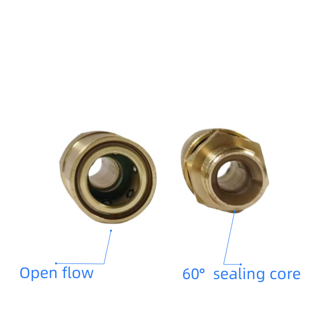
Flow configuration directly influences your machine performance. You must choose between straight-through designs and valved shut-offs based on media type. Understanding these internal mechanisms ensures you do not accidentally starve your equipment.
An open flow quick coupling provides a completely unobstructed, straight-through path. The success criteria include maximum flow rate and zero internal restriction. It entirely eliminates internal pressure drops. However, there are significant operational trade-offs. You must manually depressurize the entire system before disconnection. Open designs offer absolutely zero spill control. When you pull the sleeve back, the fluid dumps immediately. We find them best for continuous mold cooling lines. They excel in high-volume fluid transfer operations. They safely handle non-hazardous media like chilled water.
Single shut-off systems feature a valved coupler and an open plug. Their main success criteria involve preventing upstream media loss. They stop fluid flow instantly during rapid tool changeovers. An internal poppet valve springs forward to seal the line. This configuration is highly common in standard pneumatic setups. The trade-off is a moderate pressure drop across the poppet valve. Furthermore, the downstream lines will vent their remaining pressure upon disconnection. Operators will hear a brief hiss of escaping air.
Double shut-off systems feature active valves in both the coupler and the plug. Their success criteria focus entirely on zero-spill disconnection. They handle high-pressure hydraulic and hazardous chemical lines safely. Both sides seal instantly before the physical connection breaks. The main trade-off is the highest flow restriction among all types. The fluid must navigate around two internal poppet springs. You require careful calculation of manufacturer flow charts. This extra math prevents system fluid starvation during peak demands.
Flow Configuration | Internal Valve Placement | Relative Pressure Drop | Spill Control | Best Target Application |
|---|---|---|---|---|
Open Flow (Straight-Through) | None | Zero | None (Full Media Loss) | Mold cooling, bulk water transfer |
Single Shut-Off | Coupler only | Moderate | Upstream only (Downstream vents) | Compressed air tools, shop pneumatics |
Double Shut-Off | Coupler and Plug | High | Complete (Minimal fluid inclusion) | High-pressure hydraulics, aggressive chemicals |
Different industrial sectors rely heavily on specialized geometric profiles. A generic American quick coupling takes many physical forms depending on its environment. You must select the exact standardized profile for your specific application. Using visual identification charts helps engineers match these shapes perfectly.
The Industrial Interchange Standard dominates modern air systems. Formally known as MIL-C-4109 or ISO 6150-B, it serves as the baseline profile. Nearly all North American compressed air systems rely on its robust locking mechanism. The plug features a distinct, wide retaining groove. It handles high-cycle vibration from impact wrenches effortlessly. Manufacturers produce these plugs from hardened steel to prevent rapid wear. You will find them installed on almost every factory floor across the continent.
Injection molding standards focus intensely on extreme thermal management. Evaluating the proper DME standard coupling is highly critical. These unique connectors handle hot water and heated cooling oils continuously. They differ significantly from standard pneumatic profiles. The plug lengths are noticeably shorter. The internal O-ring placements sit much deeper inside the coupler body. This recessed position prevents heat degradation from the hot mold surface. Additionally, the locking sleeves often lack the automatic push-to-connect feature. They require a deliberate two-hand manual retraction. This deliberate design prevents accidental disconnections when operators accidentally bump the heavy molds.
Hydraulic flat-face profiles meet strict HTMA or ISO 16028 standards. High-pressure North American skid steers strictly require them. Heavy earth-moving equipment relies on these flush mating faces. They prevent environmental dirt contamination from entering the sensitive hydraulic pumps. Before connection, operators can quickly wipe the flat faces completely clean. More importantly, they eliminate dangerous fluid injection injuries. The locking sleeves typically feature a safety rotation lock. Once connected, you spin the sleeve to prevent accidental physical retraction.
Material choices dictate the long-term survivability of your fluid network. You must precisely align your housing materials with the specific operating environment. Making the wrong choice leads to rapid degradation and catastrophic failure.
Our practical material compatibility framework defines the following engineering standards:
Brass: This metal is ideal for water, coolant, and low-pressure air. It is highly resistant to sparking in combustible environments. Brass prevents destructive galvanic corrosion in mixed-metal piping assemblies. It machines easily and provides excellent value.
Steel and Hardened Steel: This material is mandatory for high-pressure hydraulics. It safely absorbs severe mechanical shock without deforming. Manufacturers often plate it with zinc to resist external rust.
Stainless Steel: This alloy is strictly required for corrosive chemicals. Intense washdown environments and sanitary food applications demand its high resistance. It survives harsh caustic cleaning solutions without pitting.
Internal seal and O-ring selection is equally critical to longevity. You must factor in expected temperature ranges. Chemical compatibility directly dictates the required elastomer type. Standard Buna-N (Nitrile) serves very well for general-purpose air and water. However, it hardens and cracks under extreme heat. Viton (FKM) handles high heat and aggressive petroleum chemicals effortlessly. EPDM is absolutely necessary for steam lines or automotive brake fluids. Mixing the wrong fluid with an incompatible seal causes immediate O-ring swell and connection jamming.
Follow this rigorous deployment checklist for safe and reliable implementation:
Verify the nominal size versus actual flow capacity: Do not just buy a 1/2-inch coupling for a 1/2-inch pipe. Always check the manufacturer's Cv rating. Ensure the internal poppet valve does not bottleneck your required flow rate.
Confirm thread compatibility at the manifold: Inspect the port threads carefully. Determine if they are NPT, NPTF, or an incompatible international standard. Use appropriate sealants accordingly.
Audit plug hardness to prevent coupler brinneling: Brinneling occurs when hardened locking balls indent a soft metal plug under high pressure. This creates deep grooves. Ensure you use hardened steel plugs for high-vibration applications to prevent this damage.
Final assessment logic requires strict engineering discipline. Coupling selection must prioritize rigorous thread standardisation across the entire facility. Stick definitively with NPT configurations. Ensure exact profile matching, specifically utilizing the correct DME or Industrial standards. You must always prioritize calculated flow requirements over simple nominal port sizes. This logic prevents sudden equipment stalling and reduces compressor wear.
Advise your engineering and procurement teams to take immediate action. They should audit current line pressure drops manually. They must carefully review manufacturer flow-rate and pressure-drop charts before buying replacements. Standardise your entire facility on a single recognized profile. This strategy actively prevents costly cross-contamination and dangerous connection failures. Proper selection keeps your operators safe and your fluid lines running efficiently.
A: No. While they may physically push together, the locking balls will not engage correctly. This mismatch causes severe micro-leaks. It also compromises seal integrity under dynamic loads. A sudden burst of pressure can force the plug out forcefully. Always match profiles exactly to ensure safety.
A: You must calculate the exact Cv value. Review the manufacturer’s flow chart for your specific coupling. Identify your system's required flow rate in CFM or GPM. Find the intersection on the performance chart to read the resulting pressure drop. Keep internal drops below 5 PSI for optimal efficiency.
A: High temperatures degrade standard Buna-N seals very rapidly. A connector handling hot mold coolant needs specialized O-rings. You must upgrade to Viton (FKM) seals for superior high-heat resistance. Additionally, check if thermal expansion has warped the metal housing. Replace any physically distorted plugs immediately.
A: NPT threads require external sealants like PTFE tape to prevent fluid leaks. NPTF (Dryseal) threads feature a slightly modified crest and root profile. When tightened, the threads crush together mechanically. This forms a tight, leak-free seal without needing additional tape or liquid pipe dopes.


