
close
Choose Your Site
Global
Social Media


Views: 0 Author: Site Editor Publish Time: 2026-09-16 Origin: Site


In high-pressure fluid and pneumatic systems, the point of connection is the most common point of failure. Understanding the internal mechanics of a female quick disconnect coupling is critical to preventing costly leaks, pressure drops, and system downtime. These fittings handle severe mechanical stress while keeping critical fluids securely contained.
While the male plug is typically a simple machined profile, the female socket houses complex locking mechanisms and valving. These internal components must maintain system integrity under extreme dynamic loads. You cannot rely on a simple visual inspection to gauge their reliability. Instead, you need a deep understanding of how internal geometries behave under pressure.
This guide breaks down the engineering behind these couplings. We provide the evaluation criteria needed to specify the correct component for rigorous industrial applications. You will learn how to align valve designs, seal materials, and locking styles to maximize operational safety and system efficiency.
The female coupling dictates the locking security and spill-prevention capabilities of the entire connection.
Valve design (poppet vs. flat face) directly impacts flow rate, pressure drop, and environmental contamination.
Selecting a high pressure female coupling requires aligning the internal seal materials and locking mechanisms with specific dynamic pressure ratings, not just static burst pressures.
Standardized profiles (e.g., ISO interchangeability) are critical to preventing misapplication and ensuring a leak proof coupling.
The female socket acts as the functional core of any fluid connection. It dictates how securely the plug seats and how effectively the fluid flows. We can break down its operation into three primary mechanical functions. They include the locking mechanism, the internal valving, and the seal configurations.
Most industrial sockets rely on a retracting outer sleeve. When you pull this sleeve back, it releases retaining steel balls or hardened locking pins. You then insert the male plug. The sleeve snaps forward, forcing the balls or pins into a precisely machined groove on the plug. This action locks the connection mechanically. In high-vibration environments, manufacturers often add a sleeve lock. This prevents accidental retraction if the socket bumps against an obstacle.
The internal shut-off valve is a marvel of miniaturized engineering. When you disconnect the fitting, a heavy-duty spring forces the valve closed. It presses tightly against an internal seal to prevent fluid escape. Insertion of the male plug physically pushes this valve open. The precision of this movement is crucial. If the spring is too weak, the valve may flutter under high flow rates. If it is too stiff, manual connection becomes nearly impossible.
Seals form the final barrier against pressure loss. High-pressure sockets utilize primary O-rings alongside PTFE backup rings. Fluid pressure naturally attempts to push the softer O-ring out of its groove. We call this phenomenon extrusion. The rigid PTFE backup ring sits behind the O-ring. It resists this extrusion and keeps the primary seal intact under extreme hydraulic forces.
The body material dictates the structural limit of the socket. A brass quick connect socket is highly effective for corrosive environments and moderate pressure lines. It resists water and air oxidation exceptionally well. However, severe hydraulic applications demand hardened steel or stainless steel. Brass simply lacks the tensile strength to survive high-impulse hydraulic shock waves.
Best Practice: Always evaluate the locking mechanism's ball count. A socket with more locking balls distributes the mechanical load more evenly. This reduces "brinelling" (indentation wear) on the male plug over time.
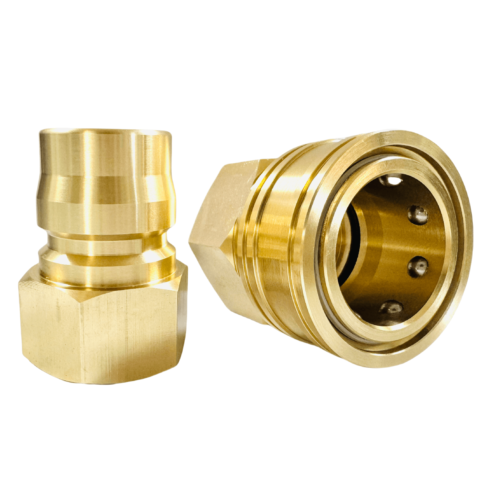
The internal valve geometry heavily influences system performance. It determines how much fluid escapes upon disconnection and how much air enters upon connection. Choosing the right valve ensures a leak proof coupling tailored to your environmental standards.
Poppet valves represent the traditional industry standard. The mechanism uses a conical or spherical valve face that presses against an O-ring.
Mechanism: The rounded face allows fluid to flow smoothly around the valve when open.
Pros: They offer excellent high flow rates. They also tolerate minor debris better than complex flat designs.
Cons: The design inherently leaves a small cavity of trapped fluid. This allows minor fluid spillage upon disconnection.
Poppet styles are best for applications where minor spillage is acceptable. You will commonly find them in agricultural equipment or heavy machinery outdoor attachments.
Flat face valves address the environmental limitations of poppet designs. They utilize flush-mating surfaces.
Mechanism: Both the male and female faces are completely flat. They wipe against each other during connection, eliminating cavities where fluid can pool.
Pros: They are essential for environmental compliance. They prevent hazardous spills and block air inclusion in closed systems.
Cons: The complex internal flow path creates a slightly higher pressure drop compared to poppet valves.
Matching the valve design to your facility requires evaluating safety standards and system sensitivity. The table below summarizes key comparison metrics.
Feature | Poppet Valve | Flat Face Valve |
|---|---|---|
Spillage on Disconnect | Moderate (Drops to Milliliters) | Virtually Zero (Film only) |
Air Inclusion | Moderate | Extremely Low |
Pressure Drop | Low | Moderate |
Contamination Resistance | Tolerates minor grit | Faces are easy to wipe clean |
Engineers often make mistakes when evaluating pressure specifications. A metal body might hold immense static pressure. However, real-world systems rarely operate under purely static conditions. Dynamic forces rapidly degrade mismatched materials.
We must differentiate between steady pressure holding and surviving "water hammer" effects. Static pressure remains constant. Dynamic pressure features violent spikes. When a system valve slams shut, fluid momentum creates a shockwave. This hydraulic shock can temporarily spike pressure to three times the normal operating level. A high pressure female coupling must absorb these spikes without deforming the locking mechanism.
High-pressure fluid lines present unique metallurgical challenges. A standard hydraulic quick disconnect typically requires a hardened steel body. Carbon steel provides the necessary fatigue resistance against continuous pressure cycling. Furthermore, manufacturers apply specialized zinc-nickel plating. This plating drastically improves corrosion resistance compared to older zinc-dichromate finishes. It prevents rust from locking the retracting sleeve in place.
The metal body handles the structural load, but the seals handle the chemistry. The internal seal material dictates the actual operational lifespan of the coupling. You must match the elastomer to the fluid and the ambient temperature.
Nitrile (NBR): The standard for petroleum-based oils. It handles temperatures from -40°F to 212°F. It fails quickly if exposed to certain synthetic fluids.
FKM (Viton): Essential for high-temperature environments. It survives up to 400°F and resists aggressive chemicals. However, it performs poorly in extreme cold.
EPDM: Required for phosphate-ester hydraulic fluids and steam lines. It handles extreme temperatures but will degrade rapidly if exposed to standard petroleum.
Common Mistake: Relying solely on the body material's pressure rating. A stainless steel socket rated for 10,000 PSI will still fail instantly if you run incompatible synthetic fluids through a standard Nitrile O-ring.
Even premium hardware fails if implemented incorrectly. System operators frequently introduce failure points through improper handling or poor specification practices. Understanding these risks helps you safeguard your infrastructure.
Operators sometimes force incompatible male plugs into female sockets. Many profiles look visually similar. For example, mixing an ISO 16028 plug with a proprietary flat-face socket might seemingly engage. However, microscopic geometric differences prevent the internal valves from opening fully. This mismatching creates massive heat generation, restricted flow, and severe seal degradation.
Connecting standard couplings while lines remain pressurized poses extreme risks. Forcing a connection against trapped pressure easily blows out the primary O-ring. The resulting seal damage leads to immediate failure upon operation. We solve this by implementing Connect-Under-Pressure (CUP) female sockets. CUP designs utilize a specialized micro-valve. This internal bleeder relieves trapped pressure internally, allowing safe engagement without damaging the primary seals.
Hoses naturally shift and bend under operational pressure. If a rigid connection point restricts this movement, it introduces side-loading. Lateral stress on a quick connect hose coupling is highly destructive. It accelerates latching-ball wear and forces the male plug sideways against the O-ring. This distortion creates a gap, leading to catastrophic high-pressure leaks. You should route hoses carefully and use swivel joints to eliminate side-loading vectors.
Industrial environments generate massive amounts of abrasive dust and metal shavings. Failure to use dust caps on a disconnected female socket invites disaster. Particulate matter settles directly onto the internal valving. When you insert the plug, you drag this abrasive grit across the primary O-ring. This scratches the elastomer and scores the metal seating surface, permanently destroying the valve's ability to seal.
Selecting the optimal fitting requires a systematic approach. You cannot simply order a replacement based on physical dimensions alone. Follow this structured process to specify the correct component for your application.
Identify the Standard: Determine the governing interchange profile. Standardized systems rely on ISO 7241 (Series A or Series B) for traditional poppet designs. Flat-face requirements typically follow ISO 16028. Establishing the standard guarantees global interchangeability and prevents proprietary vendor lock-in.
Calculate Flow and Pressure Drop: Evaluate the required GPM (Gallons Per Minute) or LPM (Liters Per Minute). Ensure the socket's internal diameter and valve style support this flow. An undersized fitting acts as an orifice, starving the system of fluid and generating excessive heat.
Define Thread and Port Types: Match the rear connection of the female socket to your existing infrastructure. Common hydraulic standards include NPT, BSPP, and SAE ORB (O-Ring Boss). Mixing thread types—such as threading an NPT fitting into a BSPP manifold—will strip threads and guarantee leakage.
Assess Operational Efficiency and Impact: Weigh the upfront implementation variables against long-term benefits. Premium flat-face couplings might represent a larger initial investment. However, they drastically mitigate fluid loss, environmental cleanup requirements, and machine downtime. Evaluate how spill reduction improves facility safety and operational uptime over a multi-year period.
A reliable female quick disconnect coupling relies on precise internal geometry, correct valve selection, and strict material compatibility. These components serve as the critical gatekeepers of your fluid systems. Understanding their retracting mechanisms, extrusion resistance, and valve dynamics empowers you to build safer environments. It also prevents premature hardware failures caused by pressure spikes and side-loading.
We highly recommend auditing current failure rates on your existing connections. Track how often O-rings blow out or how much fluid escapes during routine disconnections. This data will quickly reveal if an upgrade in valve type or seal material is required.
Take action by consulting an engineering specialist. You can also utilize digital sizing tools provided by leading manufacturers. Matching the exact dynamic specifications to your system requirements ensures maximum performance and long-term operational integrity.
A: Leaks primarily result from worn internal O-rings, severe side-loading, or scratched male plugs. Debris often damages the seal during connection. Additionally, lateral stress from tight hose routing distorts the plug's seating, creating a gap that allows high-pressure fluid to bypass the O-ring.
A: You should never attempt this with standard models. Connecting under pressure damages primary seals and creates significant physical hazards. You must use specialized CUP (Connect Under Pressure) sockets. These feature internal micro-valves that safely relieve trapped pressure during the connection phase.
A: Never rely on visual matching alone. You must check standardized ISO ratings, such as ISO 16028 or ISO 7241. Consult manufacturer interchange charts to verify exact profile compatibility. Mismatched profiles might mechanically connect but will fail catastrophically under operational pressure.
A: Brass possesses excellent corrosion resistance but lacks high tensile strength. In severe hydraulic scenarios, dynamic pressure spikes and water hammer effects physically stretch the brass body. This deformation compromises the ball-latching mechanism. High-pressure applications strictly require hardened carbon steel or stainless steel components.


