
close
Choose Your Site
Global
Social Media


Views: 0 Author: Site Editor Publish Time: 2026-07-30 Origin: Site


Engineering teams and procurement managers face a high-stakes reality every single day on the factory floor. Specifying the wrong connector routinely leads to hazardous fluid leaks, unexpected machine downtime, and severely compromised cooling efficiency. You must look far beyond the basic unit cost when sourcing these vital components. Evaluating exact engineering requirements prevents catastrophic failures during demanding production cycles. When you match components perfectly to your system, you optimize thermal performance across the board. Conversely, a poorly matched connection creates dangerous flow restrictions. This disrupts necessary thermal regulation and significantly extends cycle times in modern injection molding operations. In this detailed guide, we deliver a rigorous breakdown of standard specifications. You will discover how application variables dictate material selection and safety choices. We also outline strict criteria for evaluating potential manufacturing partners. This ensures you make a confident, data-backed purchasing decision for your facility.
Thermal regulation is the heartbeat of any successful injection molding process. When you select a connector, its internal geometry dictates how fluid moves through your system. Flow restrictions create a noticeable pressure drop, often referred to as Delta P. High Delta P means the coolant loses velocity before it even reaches the mold. This directly impacts thermal transfer rates. If the mold cannot cool the plastic fast enough, cycle times increase. Even a two-second delay per cycle cascades into massive production losses over a million-part run. Proper specification ensures your plumbing does not act as a bottleneck.
Under-specifying components introduces hidden operational burdens. Facilities often face premature seal wear, unexpected fluid loss, and severe safety hazards during tool changeovers. When seals degrade faster than anticipated, maintenance teams must stop production to replace them. Leaking coolant also creates slip hazards on the factory floor. These daily maintenance realities destroy operational efficiency. Operators waste valuable labor hours fighting equipment rather than producing parts. Choosing robust components from the start eliminates these constant, frustrating interruptions.
Injection molding involves extreme temperatures and dynamic pressures. In these environments, you must over-index on durability. A catastrophic leak in a high-temperature thermal oil system is not just messy; it is a severe safety incident. Risk mitigation requires components engineered to handle thermal spikes and mechanical vibrations. By prioritizing high-grade materials and secure locking mechanisms, you protect your personnel and your capital equipment. Engineering teams should always specify components with safety margins that exceed standard operating parameters.
Industry professionals rely on the S.T.A.M.P. methodology to prevent costly sizing and material errors. This framework forces you to evaluate every critical variable before finalizing a purchase.
Selecting the proper cooling circuits mold quick coupling begins with flow capacity. You must analyze flow curves and Cv values (flow coefficients). The Cv value tells you exactly how much fluid can pass through the valve at a specific pressure drop. If you ignore this metric, the connector easily becomes a bottleneck. You must also match thread standards accurately. Intermixing NPT, BSPT, and Metric threads causes immediate galling and leakage. Always verify internal passage dimensions against your primary manifold hoses.
Heat degrades inferior materials rapidly. You must evaluate both continuous operating temperatures and peak thermal spikes. Systems utilizing water behave very differently than those pumping thermal oils or glycol mixtures. Seal selection is paramount here. The chemistry of your fluid dictates your elastomer choice.
| Seal Material | Optimal Fluid Compatibility | Maximum Temperature Range | Common Mistakes |
|---|---|---|---|
| Nitrile (Buna-N) | Standard water, mild oils | Up to 212°F (100°C) | Using in high-heat oil systems |
| EPDM | Hot water, steam, glycol | Up to 300°F (150°C) | Exposing to petroleum-based oils |
| Viton (FKM) | Thermal oils, harsh chemicals | Up to 400°F (200°C) | Specifying for standard cold water (over-engineering) |
Your application determines the internal mechanics of the connector. You generally choose between valved and non-valved designs. Non-valved, straight-through designs offer maximum flow rates and zero pressure drop. However, they spill fluid during disconnection. Valved models, featuring single or double shut-off mechanisms, prevent zero-spillage during tool changes. Double shut-off valves trap fluid in both the socket and the plug. You must balance the need for a clean workspace against the requirement for unrestricted fluid velocity.
Material choices directly impact durability. Brass remains the standard for traditional water cooling due to its excellent machinability and moderate corrosion resistance. However, cleanrooms and corrosive fluid applications demand Stainless Steel. Stainless steel resists chemical degradation and withstands higher mechanical abuse. Recently, advanced engineered composites and plastics have entered the market. They offer exceptional weight reduction and cost-efficiency. You must weigh the harshness of your factory environment against the upfront cost of premium metals.
Never size a connector based solely on normal working pressure. You must build in a substantial burst pressure safety margin. Dynamic fluid systems experience hydraulic shock, commonly known as water hammer. When a valve closes rapidly, fluid momentum creates a massive pressure spike. If your connector lacks the structural integrity to absorb this shock, the locking mechanism will fail. Always verify that the manufacturer tests their components for cyclic pressure fatigue, not just static loads.
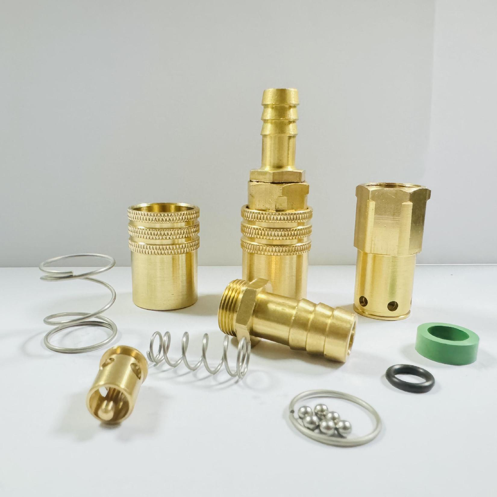
Modern manufacturing requires rapid tool changeovers to remain competitive. Ergonomics play a massive role in this efficiency. Push-to-connect mechanisms allow operators to secure lines with one hand. This saves valuable seconds per connection. Conversely, manual sleeve retraction requires two hands and greater physical effort. For facilities executing high-frequency mold changes daily, push-to-connect designs drastically reduce operator fatigue. Better ergonomics lead to faster, more secure connections.
Tight, high-vibration manifold environments pose a unique threat. Standard sleeves can vibrate loose or snag on adjacent hoses during operation. This causes accidental disconnections, spraying hot coolant across the machine. To combat this, specify connectors with integrated sleeve locks. These safety-release systems require a deliberate twist-and-pull motion to disengage. They provide peace of mind in densely packed tooling areas where visual inspection is difficult.
Assess the ambient conditions surrounding your injection molding machines. Factory floors generate airborne dust, abrasive debris, and external mechanical impacts. If a socket sits exposed, debris easily infiltrates the locking balls and internal O-rings. This contamination prevents the valve from seating properly. In these harsh scenarios, you should specify ruggedized coupling bodies or utilize protective dust caps and sleeving. Protecting the connection point extends the operational lifespan of the entire cooling circuit.
Standard catalog options resolve most cooling challenges, but they cannot fix everything. Sometimes, you encounter highly complex manifold spacing that standard sockets simply cannot fit into. Extreme temperature variances or proprietary fluid blends also push standard seals past their failure points. When your engineering parameters fall outside typical operating ranges, forcing a standard part into the system guarantees failure. Identifying these non-standard requirements early prevents costly machine modifications down the road.
Bespoke engineering requires upfront capital. Custom designs carry longer lead times and higher initial prototyping costs. However, you must weigh these upfront costs against long-term operational gains. A customized geometry might eliminate an elbow joint, drastically improving flow velocity. This improved flow reduces your cycle time by several seconds. Over a year of continuous production, the reduced scrap rates and increased part output easily justify the initial engineering investment. Customization solves root-cause inefficiencies.
If you design a bespoke solution for one machine, you must ensure it scales. A highly specialized part is useless if the manufacturer cannot reproduce it consistently. Work closely with your engineering partner to guarantee they hold the tight tolerances required for mass production. Standardize this custom component across multiple facilities to simplify your spare parts inventory. Scalable custom solutions transform a single machine's advantage into a company-wide competitive edge.
A supplier is only as good as their quality control department. You should demand total transparency regarding their batch testing protocols. Ask for documentation on burst pressure validation and cycle testing. Reliable manufacturers readily provide material certifications ensuring ISO compliance. If a vendor hesitates to share their testing methodologies, you should look elsewhere. Rigorous testing prevents defective batches from ever reaching your facility.
Even the most durable components eventually require replacement seals or spare plugs. Your chosen supplier must demonstrate impressive inventory depth. Assess their standard lead times for critical replacement parts. A global availability network is crucial if you operate facilities in multiple countries. A minor seal failure should never cause a manufacturing bottleneck because a vendor cannot ship parts quickly. Partner with suppliers who prioritize robust logistics.
Evaluating a supplier goes beyond flipping through a product catalog. You need a partner, not just a distributor. The best suppliers offer dedicated application engineering assistance. They help you run flow rate calculations and provide detailed fluid compatibility charts. Follow these key steps when vetting their engineering support:
Suppliers who engage in the engineering phase help you catch specification errors before purchase orders are signed.
Rigorous specification at the procurement stage serves as a direct investment in facility uptime. Do not let a minor component cause major production delays. Consult with an engineering specialist today, download a technical sizing guide, and request a customized quote based on your specific flow parameters to secure the right mold quick coupling for your operations.
A: A single shut-off coupling contains a valve only in the socket, stopping fluid flow on one side when disconnected. It offers higher flow rates but allows minor spillage from the plug side. A double shut-off coupling features valves in both the socket and plug. This prevents fluid spillage entirely, keeping workspaces safe and clean, though it slightly restricts overall flow velocity.
A: You calculate proper flow size using the Cv value (flow coefficient) provided by the manufacturer. This metric indicates how much fluid passes through the connector at a specific pressure drop (Delta P). You must review pressure drop charts to ensure the selected size meets your manifold's required gallons-per-minute (GPM) without creating a bottleneck in the cooling circuit.
A: FKM (commonly known as Viton) is the optimal seal material for high-temperature thermal oils. It withstands extreme heat up to 400°F (200°C) and resists chemical degradation from synthetic oils. Nitrile and EPDM will quickly harden, crack, or swell if exposed to thermal oils, leading to catastrophic leaks. Always verify peak operating temperatures before finalizing seal selection.
A: No. Mixing and matching plugs and sockets from different manufacturers is highly dangerous. Even if the profiles appear visually similar, microscopic differences in locking ball grooves and internal tolerances exist. Cross-brand mixing causes premature seal wear, unexpected disconnections, and severe fluid leaks. Furthermore, intermixing parts instantly voids all manufacturer warranties and liability coverage.


