
close
Choose Your Site
Global
Social Media


Views: 0 Author: Site Editor Publish Time: 2026-07-21 Origin: Site


Injection molding setups often suffer from severely restricted spatial clearances. You routinely encounter tight spaces between the mold base and the heavy machine platen. Operating within these cramped confines makes efficient cooling a constant challenge. Here, the 90 degree mold coupling acts as a critical fluid control component. It routes cooling lines safely and efficiently without risking dangerous hose kinks. It also prevents unwanted flow restrictions during high-pressure cycles.
This article serves as a comprehensive technical and commercial evaluation guide. Tooling engineers and procurement managers will learn how to select or replace HASCO standard cooling components effectively. You will discover vital specifications, material engineering choices, and precise performance evaluation criteria. By the end, you will know exactly how to optimize your injection molding cooling circuits for maximum reliability and spatial efficiency.
Spatial Efficiency: 90-degree configurations prevent hose kinking and optimize platen clearance in tight injection molding environments.
Profile Standardization: A true HASCO standard mold coupling guarantees interoperability across the cooling circuit, reducing mold changeover times.
Material Selection: Choosing the right brass mold coupling or stainless steel variant depends directly on coolant type, pressure, and temperature requirements.
Evaluation Criteria: Decision-makers must weigh OEM precision against the cost and lead-time benefits of high-quality, verified compatible alternatives.
Standard straight connectors often cause significant problems in cramped spaces. They force cooling hoses into severe bend radii. This unnatural bending frequently leads to restrictive kinks. Operators often bend hoses sharply to fit them inside safety gates. This sharp bending creates a dangerous pinch point. The hose wall collapses inward. Fluid velocity drops dramatically. As a result, you face dangerous flow restrictions and uneven mold temperatures. Inconsistent temperatures inevitably cause warped molded parts and longer overall cycle times.
How do we solve this spatial dilemma? An angled coupling redirects fluid flow immediately at the mold surface. It changes the fluid direction inside the solid metal body before the flexible hose even begins. This smart redirection minimizes the overall spatial footprint. Hoses now drop straight down, running parallel to the mold face rather than jutting outward. This elegant routing eliminates the need for excessive platen clearance.
To achieve success, these components must meet strict fluid dynamics criteria. Maintaining consistent turbulent flow is your primary objective. Laminar flow acts as a thermal insulator. It prevents efficient heat transfer. You need turbulent flow to scrub heat away from the mold steel effectively. To achieve proper heat transfer, cooling water must maintain a Reynolds number above 4,000. A well-designed angled connector minimizes internal restriction. It ensures the water velocity remains high enough to sustain this critical turbulence. Additionally, they must ensure zero-leakage operation. High-pressure injection cycles demand absolute seal integrity.
Ultimately, this component serves as the essential mold cooling connector. It builds a highly reliable bridge between two distinct operational zones. On one side, you have the mold's internal drilled channels. On the other side sits the external temperature control unit (TCU). A failure at this bridge stops production entirely.
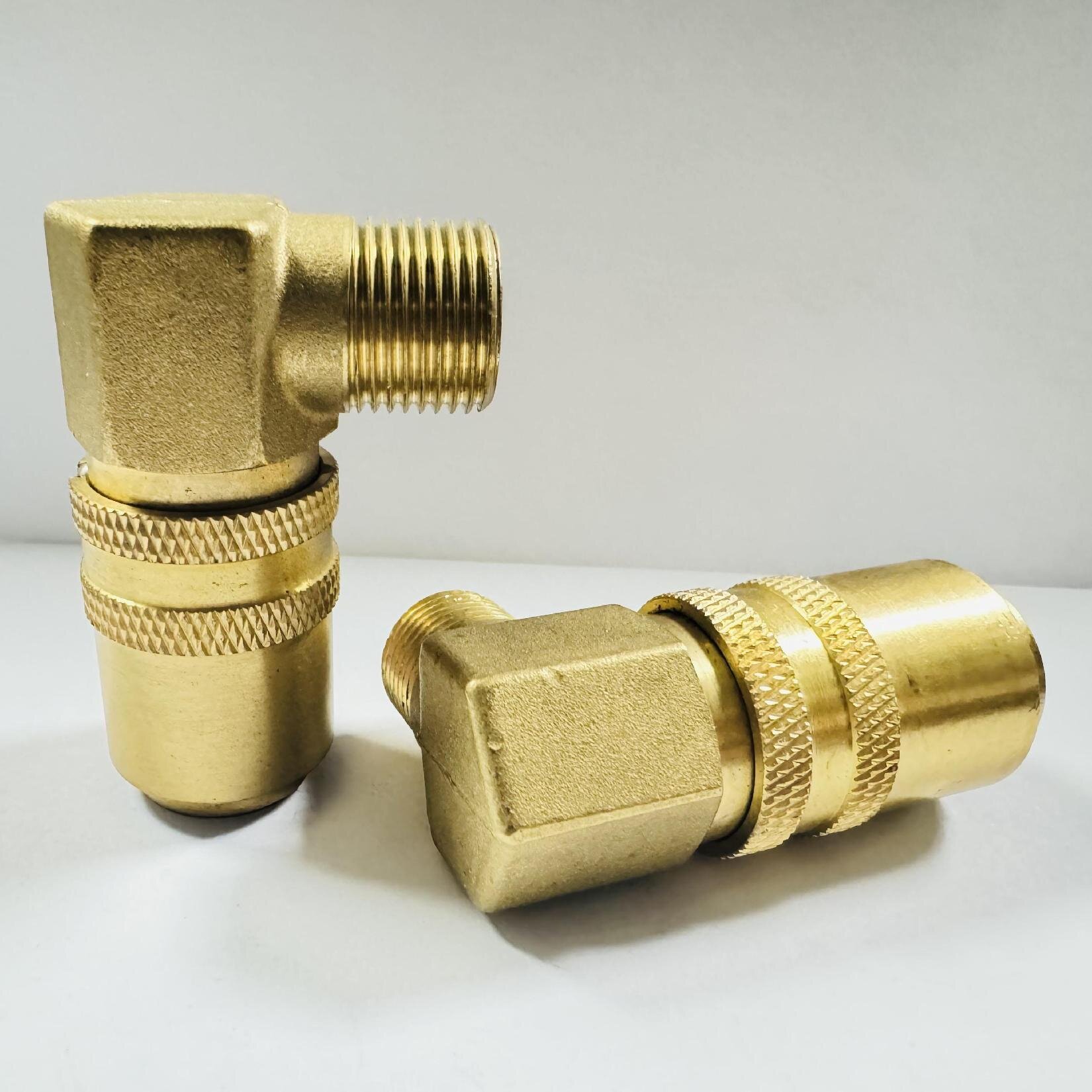
What defines a true HASCO standard mold coupling? It centers on a highly specific locking mechanism and plug profile. The industry widely recognizes this as the Z-series compatibility standard. Tooling engineers instantly recognize its distinct shape. The socket utilizes a precise ball-locking collar. Retaining ball bearings drop perfectly into the corresponding groove on the plug nipple. A spring-loaded outer sleeve slides forward to lock them permanently in place. This guarantees a secure, leak-free connection under intense pressure.
Material engineering dictates operational limits and longevity. The standard brass mold coupling remains the most common choice globally. Brass offers excellent thermal conductivity. It handles standard water and glycol mixtures flawlessly. It provides a highly cost-effective solution for standard molding operations. However, aggressive environments demand better materials. You must upgrade to stainless steel under specific conditions. Corrosive water supplies degrade brass quickly. High-temperature synthetic thermal oil circuits require the superior structural integrity of stainless steel. Cleanroom medical molding strictly prohibits brass oxidation. Stainless steel eliminates particulate shedding entirely in these sensitive environments.
Material Type | Primary Application | Maximum Temperature Limit | Corrosion Resistance Level |
|---|---|---|---|
Standard Brass | Chilled Water / Standard Glycol | 150°C (302°F) | Moderate |
Stainless Steel | High-Temp Oil / Medical Cleanroom | 250°C+ (482°F+) | Superior |
Connection interfaces require precise matching to prevent catastrophic leaks. On the mold side, you typically install a male thread coupling. Engineers specify different thread standards globally. Europe favors BSP (British Standard Pipe). North America relies heavily on NPT (National Pipe Thread). Asia frequently utilizes Metric threads. You cannot mix these thread profiles. NPT threads rely on the deformation of the thread taper to seal tightly. BSP threads often use a bonded seal washer. Mismatched threads will inevitably leak under pressure.
On the hose side, you choose between two primary designs. Push-lok barbs grip the interior hose wall aggressively. They require no external clamps for secure line retention. Standard hose tails feature softer barb profiles. They absolutely require heavy-duty external hose clamps to secure the lines safely.
You must evaluate performance specifications rigorously before finalizing your purchase. Specifying the correct HASCO quick coupling requires careful calculation. First, you must choose between valved and unvalved systems based on your changeover procedures.
Valved Systems: These feature an internal spring-loaded poppet valve. The valve closes automatically upon disconnection. This prevents coolant spillage onto the tool or machine bed. It keeps your workspace safe and dry. However, the internal valve creates a slight physical obstruction. It introduces a higher initial cost and a measurable flow restriction.
Unvalved Systems: These offer a completely open internal fluid pathway. They provide the maximum possible flow rate. You achieve superior turbulent flow easily. They cost less upfront. However, you must drain the entire cooling circuit before disconnection. Failing to drain the system results in massive coolant spills on the shop floor.
Pressure and flow dynamics demand dedicated engineering attention. Every angled turn introduces a pressure drop. Fluid hits the internal angled wall and loses kinetic energy. You must calculate this acceptable pressure drop carefully. Engineers use the flow coefficient (Cv) value to understand this metric. The Cv value tells you exactly how much water flows through the fitting at a specific pressure drop. Ensure your TCU pump can still deliver the required Gallons Per Minute (GPM). If the flow drops too low, the mold overheats. Cycle times increase. Part quality suffers immediately.
Seal and O-ring integrity dictate long-term operational reliability. Standard couplings utilize FKM or Viton seals. These handle typical molding temperatures perfectly. They resist chemical degradation from standard water and glycol mixtures. However, extreme applications require specialized materials. High-heat oil circuits destroy standard rubber quickly. You must evaluate high-temperature fluorocarbon alternatives for extreme thermal applications.
The current market reality offers tooling managers many choices. You can easily find compatible components globally. Many third-party manufacturers produce these specific profiles. They reverse-engineer the external dimensions to match the recognized standard.
However, you must conduct a severe risk assessment. Poorly machined knock-offs threaten your entire molding operation. They often suffer from inconsistent manufacturing tolerances. A plug might be a fraction of a millimeter too wide. It will fail to lock correctly inside an existing socket. This causes catastrophic leaks during a high-pressure cycle. Water spraying onto a hot mold causes instant thermal shock. It can also cause severe electrical shorts in hot runner systems. Pressure drops from poorly designed internal pathways are equally dangerous.
You need a reliable shortlisting logic. Follow these established guidelines:
Strictly specify official OEM parts for complex multi-coupling plates.
Use OEM parts for highly sensitive, validated medical molds.
Evaluate vetted compatible alternatives for standardized high-volume production runs.
Consider compatible brands to overcome localized supply chain delays.
Leverage high-quality alternatives for significant cost-at-scale considerations.
Verification separates good investments from dangerous mistakes. Never buy bulk components blindly. Always request official material certificates from the vendor. Demand documented dimensional inspection reports. High-quality alternative manufacturers use coordinate measuring machines (CMM). This verifies the locking groove angle down to the micron. Procure a small sample batch first. Test them aggressively on a non-critical tool before full deployment.
Proper installation prevents premature failures on the production floor. Installation best practices begin with correct tooling at the bench. Technicians must use properly calibrated torque wrenches. Proper torque specifications prevent severe brass deformation. Over-tightening crushes the internal fluid passage. It can also strip the threads out of the softer mold steel. Under-tightening guarantees a slow, messy leak.
Sealing protocols require an objective operational analysis. Many shops still rely on traditional Teflon tape. It lubricates the threads nicely during installation. It fills microscopic gaps effectively. However, tape introduces a severe hidden risk. Frayed tape fragments often shear off during insertion. They enter the internal cooling circuit. These tiny fragments travel until they find a bottleneck. They frequently clog delicate bubblers or thin cooling baffles.
Liquid thread sealants offer a vastly superior alternative for mold-base applications. You apply a small drop to the leading threads. It cures anaerobically into a solid plastic seal. They require about 24 hours to reach full strength. This solid seal resists high-frequency machine vibration perfectly. It never shreds or fragments into the water lines.
Preventative maintenance extends component life dramatically. You must establish strict routine inspection intervals. Technicians should inspect O-rings monthly for flattening or chemical degradation. They must check the locking sleeve springs for smooth retraction. Finally, they need to monitor internal pathways for hard mineral buildup. Hard water scaling restricts flow severely over time. Calcium deposits coat the inside of the elbow. Regular descaling flushes keep these vital pathways wide open. You can also drop scaled fittings into an ultrasonic cleaning bath. The high-frequency waves shatter the calcium deposits without damaging the brass.
Specifying the right components requires a delicate operational balance. You must evaluate spatial constraints meticulously. You must calculate critical flow requirements accurately. Material compatibility ultimately dictates your final selection. The correct choice prevents unplanned downtime completely. It ensures consistent, high-quality molded parts.
Take decisive action to optimize your cooling circuits today. First, review your current TCU pressure logs immediately. Look for unexplained flow drops or pressure spikes. Next, audit your existing mold clearances. Identify any dangerously bent or stressed hoses. Finally, request comprehensive cross-reference specification sheets from your suppliers. Validating compatibility before purchase guarantees seamless integration on your busy shop floor.
A: The difference lies entirely in their physical plug profiles. A HASCO plug features a distinctly different nipple length. Its locking groove sits at a different position compared to a DME plug. The two standards are fundamentally incompatible. They will not lock together safely without using a dedicated, specialized adapter fitting.
A: Yes, it introduces minor fluid turbulence. It creates a measurable pressure drop compared to a straight flow fitting. Fluid loses energy when striking the internal angled wall. Tooling engineers must account for this specific resistance in their overall cooling circuit calculations to ensure adequate heat transfer.
A: While technically possible, it introduces an unnecessary variable. If the third-party manufacturer strictly adheres to the exact profile, they will connect. However, minute tolerance stacking can compromise long-term seal reliability. We highly recommend testing a small sample batch rigorously before authorizing a full-scale deployment.
A: The limit generally depends on the internal O-ring material. Standard Viton seals typically handle temperatures up to 200°C (392°F). However, the structural integrity of the specific brass alloy under high pressure also matters. You must verify the absolute thermal limits via the manufacturer's official technical datasheet.


