
close
Choose Your Site
Global
Social Media


Views: 0 Author: Site Editor Publish Time: 2026-08-07 Origin: Site


Incorrectly sized connectors on ejection molds do not just leak. They trigger drastic pressure drops. They extend cycle times significantly. They risk severe equipment damage during high-pressure core pulls or ejection phases. Proper sizing requires much more than simply matching thread dimensions. It requires carefully aligning flow rates, pressure tolerances, and profile standards. You must match these variables to the exact demands of your injection molding presses. We provide an engineering-level, step-by-step framework below. It helps you accurately measure, evaluate, and select the optimal fluid connector. You will learn how to achieve seamless integration. You will also discover how to maximize machine uptime consistently.
Undersized connections act as severe flow restrictors in your hydraulic circuits. They create immediate bottlenecks. Restricted fluid flow generates excessive, localized friction. This friction quickly heats the hydraulic oil. The entire cooling and ejection system loses efficiency. Mold ejection cycles suffer noticeable delays. These repeated delays severely damage overall production yields.
Optimal sizing eliminates these compounding issues. An accurately sized ejection molds hydraulic quick coupling guarantees zero pressure drop under peak loads. It completely prevents fluid loss during changeovers. It also fits perfectly inside tight spatial constraints on the mold platen. You achieve a reliable, high-performance ejection stroke every time.
We must acknowledge operational realities on the shop floor. Operators constantly risk cross-connecting fluid lines. This happens often on highly complex multi-cavity molds. Proper sizing strategies prevent these costly errors. Color-coding identical connections also helps operators navigate confusing setups. These methods enable rapid, error-free mold setups. They directly support Single-Minute Exchange of Die (SMED) initiatives. Machine changeovers become safer and significantly faster.
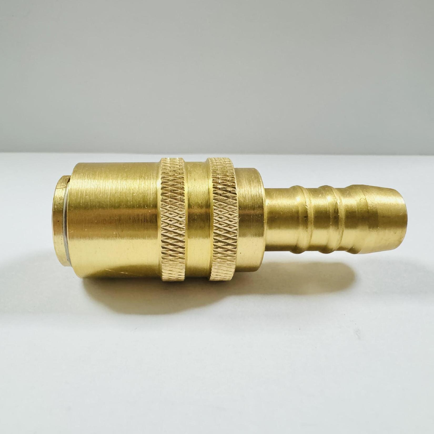
You cannot replace an existing connector accurately without precise measurements. Follow this standard operating procedure. It removes guesswork. It guarantees direct interchangeability for your maintenance teams.
Gather the correct inspection tools first. Do not use rulers or tape measures.
Determine the port connection on the machine side. Measure the male thread OD carefully. Alternatively, measure the female thread ID if applicable. Note the exact decimal reading from your calipers. Use your pitch gauge to identify the threads per inch.
Cross-reference your results against standard industrial thread charts. Compare the data against NPT, BSPP, SAE ORB, or Metric categories. This step confirms your precise port connection type. It prevents cross-threading during installation.
Next, evaluate the plug diameter. The plug is the male nipple segment. This measurement determines the actual body size. Standard sizes often include 1/4", 3/8", or 1/2". A 1/2" thread does not always mean a 1/2" body size. Do not confuse the two.
Identify your specific profile design. Flat face designs are spill-free. Poppet valves are common for general hydraulics. Straight-through designs offer maximum flow but lack internal shut-off valves. A standard hydraulic quick coupling follows strict ISO specifications. ISO standards dictate exact external dimensions. You need these exact dimensions to ensure reliable interchangeability across different press machines.
Matching physical dimensions is only the first step. You must evaluate internal fluid dynamics. Ignoring performance specifications leads to catastrophic component failures during high-stress ejection cycles.
Calculate the required fluid flow rate for your ejection cylinder. Match the Cv value (flow coefficient) to this exact requirement. Your connector must handle peak volume effortlessly. We recommend never exceeding a 10-15 PSI pressure drop. High pressure drops rob your system of ejection power. They create sluggish mechanical movements.
Ejection mechanisms create sudden pressure spikes constantly. These spikes far exceed normal operating parameters. Review your hydraulic quick coupling specifications carefully. The maximum working pressure of the unit must surpass peak system pressure. Do not rely solely on continuous operating pressure limits. A connector rated for 3,000 PSI continuous might fail if spikes hit 5,000 PSI repeatedly.
Evaluate your base metal choices. Carbon steel is standard for general hydraulic oil. Stainless steel resists corrosion in harsh or wet environments. You must also match the internal seal material to your fluid type.
Seal Material Compatibility Guide
| Seal Material | Primary Fluid Compatibility | Temperature Range (Approximate) | Common Application |
|---|---|---|---|
| Buna-N (Nitrile) | Standard Hydraulic Oil, Water | -40°F to 250°F | General injection molding presses |
| Viton (FKM) | Synthetic Fluids, High Heat | -15°F to 400°F | High-temperature molds |
| EPDM | Phosphate Ester, Skydrol | -65°F to 300°F | Specialty fire-resistant fluids |
Choosing the wrong seal causes rapid degradation. The elastomer will swell, crack, or dissolve completely. This mistake guarantees massive fluid leaks onto your shop floor.
Engineers must decide between catalog parts and custom-machined solutions. Both options serve distinct operational purposes. You must analyze your exact mold constraints first.
Standard ISO profiles offer fantastic reliability. You should rely on standardized options like ISO 16028 or ISO 7241. They work perfectly for standard injection presses. These catalog parts deliver high cost-efficiency. Distributors stock them globally. They guarantee immediate availability for emergency repairs. Standardization reduces inventory complexity drastically.
Sometimes off-the-shelf catalog parts fail to fit. Ultra-compact spaces demand a specialized approach. You might need a highly specific custom hydraulic quick coupling. Multi-coupling plates allow operators to connect ten lines simultaneously. Unique angle blocks fit awkward mold clearances perfectly. Custom lengths bypass thick platen walls.
We must state transparent assumptions here. Custom engineering naturally increases upfront lead times. Custom parts cost more initially. However, custom designs drastically reduce long-term mold changeover times. They eliminate cramped, dangerous manual connections. They cut maintenance downtime significantly over the lifespan of the press.
Procuring high-pressure fluid connectors is not a simple commodity transaction. Your manufacturing uptime depends on supplier competence. Use strict evaluation criteria before finalizing any vendor agreements.
Prioritize manufacturing partners who offer rapid prototyping for custom needs. They should iterate designs quickly. Furthermore, ensure they maintain deep local inventory. Local stock is mandatory for standard wear-and-tear replacements. You cannot wait four weeks for a replacement valve while a critical press sits idle.
Properly sizing fluid connectors requires balancing physical dimensions and internal fluid dynamics. You must calculate flow coefficients and anticipate pressure spikes. You must also respect the spatial constraints of the ejection mold itself. Selecting the wrong profile creates dangerous leaks and costly cycle delays.
Take immediate action on your shop floor. Audit your current mold connections using digital calipers and a thread pitch gauge. Document your findings clearly. Contact an application engineer if you discover flow bottlenecks. Have them review your specific ejection flow requirements before you begin procurement.
A: Look closely at the thread profile. NPT threads are tapered. They become narrower toward the tip to create a mechanical seal. BSPP threads are parallel. They remain uniform in diameter and require an O-ring or bonded washer to seal properly. You can verify the exact difference using a thread pitch gauge.
A: You should avoid mixing different brands whenever possible. Cross-branding risks microscopic tolerance mismatches. This causes weeping under high pressure. If mixing is unavoidable, strict adherence to universal ISO standards (like ISO 16028) is mandatory to ensure basic safety and interchangeability.
A: Flow restriction usually stems from an undersized body diameter. Confusing thread size with body size causes this mistake. Improper internal valve seating also creates bottlenecks. Finally, choosing a connector with a mismatched Cv value limits fluid passage, starving the cylinder of needed hydraulic power.


