
close
Choose Your Site
Global
Social Media


Views: 0 Author: Site Editor Publish Time: 2026-08-19 Origin: Site


Unreliable fluid connections in injection molding or thermal management systems often lead to costly downtime. They cause hazardous leaks and inconsistent cycle times. We recognize this harsh industrial reality across manufacturing floors. Engineering teams need reliable components to maintain continuous production. We designed this guide to provide a clear, objective framework. You will learn how to evaluate and select the right connector profiles. Specifically, we dissect the RPL and RMI series in detail. You require robust temperature control and rapid mold changes. You also need verifiable fluid compatibility for daily operations. Standardizing your equipment choices minimizes errors. This article reveals exactly how these specialized profiles deliver consistent results. You will discover practical strategies for maximizing system integrity and operational uptime.
System Integrity: French standard quick couplings prioritize operator safety and zero-leak performance, specifically engineered for the high-cycle demands of mold temperature control.
Series Distinction: RPL quick couplings are optimized for high-temperature fluid circuits with push-button disconnects, while RMI quick couplings offer versatile, high-flow capabilities across varying pressure dynamics.
Material Longevity: Specifying a nickel plated brass coupling ensures essential corrosion resistance and thermal stability against harsh cooling fluids or hot oils.
Operational Efficiency: Push lock coupling mechanisms significantly reduce tooling changeover times by enabling secure, one-handed, blind connections in tight mold spacing.
Injection molding and die-casting operations require frequent tool changes. Traditional threaded fittings severely slow down these transitions. They often result in fluid loss and hazardous thermal spills. Plant operators face extended setup times when manually unthreading hot lines. You need a faster, safer alternative to keep machines running. Threaded profiles simply cannot support high-frequency mold changeovers safely. Engineers must eliminate these bottlenecks to optimize cycle efficiency.
Mechanically, a French standard quick coupling differs significantly from ISO 7241 profiles. ISO standards often dictate broad hydraulic applicability. French standard profiles focus heavily on temperature regulation geometries. They utilize a distinct plug-and-socket locking architecture. This specific geometry ensures tight tolerances during high-temperature expansion. Interchangeability relies on matching these precise physical dimensions. Many facilities reference Stäubli profiles as the baseline for this standard. The design intentionally prevents lateral play during thermal cycling.
The French mold coupling has become the default architecture for precision temperature regulation. Injection molds cycle rapidly between intense heating and cooling phases. The coupling must endure severe thermal shocks without degrading. It provides unrestricted flow channels to maximize heat transfer efficiency. Operators rely on this design to maintain exact mold temperatures. Consistent temperature control directly translates to higher part quality. We see fewer part rejections when mold temperatures remain perfectly stable.
Advanced sealing architectures set these components apart. They employ flush-face and non-spill valving designs. Flush-face valves eliminate dead spaces where fluid could pool. This prevents air inclusion when connecting the lines. It also eliminates fluid spillage upon disconnection. Operators stay safe from scalding fluids or slick floors. Non-spill mechanisms utilize internal springs to instantly close the flow path. You maintain a clean environment while protecting personnel from chemical exposure.
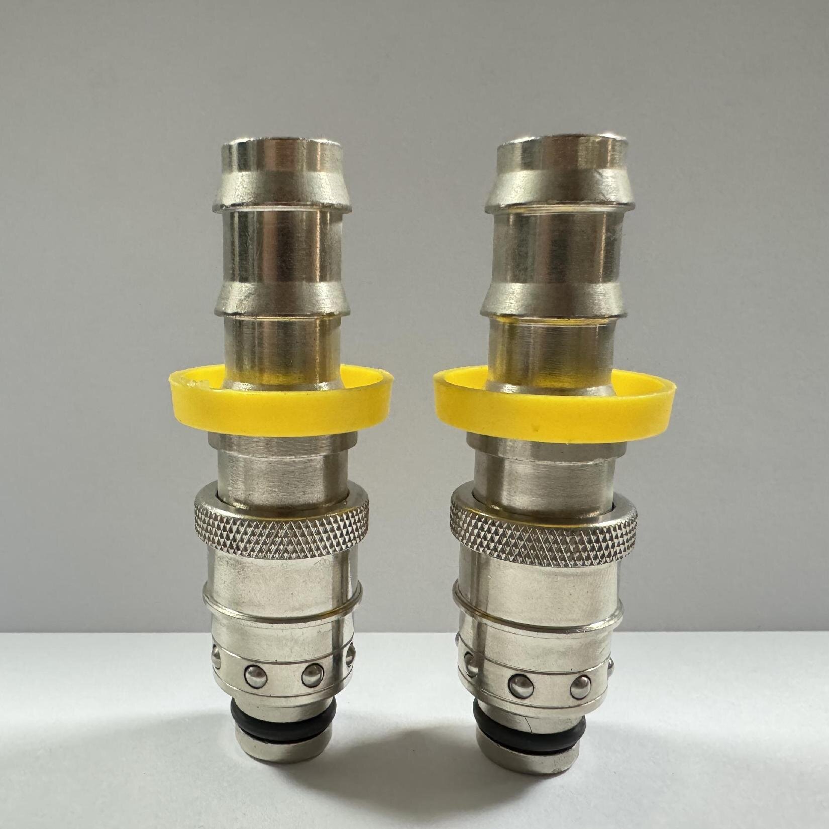
Understanding series distinctions helps engineers specify the correct component. Both profiles serve thermal management systems but handle different dynamics. They feature distinct locking mechanisms and flow characteristics. We must evaluate them based on their primary operational strengths.
The RPL quick coupling utilizes strict internal valving and a flush-face design. The secure locking mechanism relies on high-strength retention balls. These components maintain a rigid hold under high-pressure spikes. The flush-face geometry practically eliminates any fluid loss during uncoupling. This profile excels in absolute leak prevention.
We see the RPL series deployed in demanding high-temperature environments. It serves hot oil circuits and highly pressurized water lines. Operator safety remains non-negotiable in these applications. Scald prevention drives the engineering behind the RPL design. The action mechanism requires a deliberate push-button release. You cannot accidentally disconnect the line by bumping the sleeve. This conscious action requirement protects technicians working near hot molds.
The RMI quick coupling focuses heavily on maximum flow capacity. It features a streamlined internal path to achieve a lower pressure drop. The robust locking sleeve withstands aggressive handling during rapid changeovers. You will find fewer internal flow restrictions compared to flush-face alternatives. It delivers high volumes of fluid efficiently.
Facilities use the RMI series for general temperature control. It connects centralized cooling water manifolds to multi-coupling plates. The profile handles the repetitive demands of standard water cooling easily. The action mechanism features a collar-based release. Operators simply pull back the collar for quick, repetitive disconnections. This speeds up routine maintenance on large cooling blocks.
You must match the coupling series to specific operational outcomes. Consider your required flow rates, thermal extremes, and changeover frequency. RPL profiles suit safety-critical, high-temperature oil applications. RMI profiles suit high-volume, rapid-cycle water applications. We summarize the key operational differences below.
Feature | RPL Series | RMI Series |
|---|---|---|
Primary Application | High-temp oil, pressurized water | General cooling, water manifolds |
Locking Mechanism | Push-button release | Collar pull-back release |
Flow Characteristic | Controlled, zero-spill flush face | High capacity, low pressure drop |
Safety Focus | Prevents accidental disconnects | Enables rapid, repetitive cycling |
Raw brass presents significant problems in modern manufacturing environments. Standard brass suffers from dezincification when exposed to aggressive industrial water. Zinc leaches out of the alloy over time. This leaves a porous, weakened copper shell behind. Oxidation further degrades standard brass in glycol mixtures. High-temperature synthetic oils also accelerate the breakdown of untreated metals. You risk catastrophic component failure if you ignore these chemical reactions.
Specifying a nickel plated brass coupling solves these material vulnerabilities. The plating process fundamentally alters the surface hardness. It creates a robust barrier against harsh fluid media. Nickel plating effectively mitigates galvanic corrosion. This occurs when dissimilar metals interact within the fluid system. The protective layer drastically extends the lifespan of the coupling body. You gain the machinability of brass alongside the chemical resistance of nickel.
We must evaluate internal components just as strictly. The brass body only forms the outer shell. Internal springs and locking balls endure constant mechanical stress. Manufacturers usually forge these internal parts from high-grade stainless steel. Stainless steel resists rust and maintains spring tension at extreme temperatures. A strong nickel-plated shell requires equally resilient internal mechanics. Weak internal springs will cause premature leakage regardless of exterior plating.
Seal material compatibility dictates the ultimate success of the connection. You must match the elastomer strictly to the fluid media. Consider the peak operating temperature to avoid premature seal degradation.
FKM (Viton): Excellent for high-temperature synthetic oils. It withstands intense heat but struggles with hot steam.
EPDM: The optimal choice for hot water and glycol mixtures. Never use EPDM with petroleum-based oils. It will swell and fail rapidly.
NBR (Nitrile): Best suited for standard hydraulic oils and general water cooling at moderate temperatures. It lacks extreme high-temperature resistance.
Safety and ergonomics define modern tooling setups. A reliable push lock coupling transforms how technicians manage connections. Molds often feature incredibly tight spacing. Visual confirmation of a secure lock proves impossible in these blind spots. The push lock design relies on distinct tactile feedback. Operators feel a solid mechanical click when the plug seats properly. This tactile guarantee prevents partially connected lines from blowing out under pressure.
We must engineer systems to prevent accidental disconnects. Factory floors experience heavy vibration and sudden pressure surges. Accidental tool strikes frequently hit exposed fluid lines. The structural features of a push lock mechanism resist these external forces. The locking balls wedge firmly into the plug groove. The outer sleeve requires specific directional force to release. Vibration alone cannot dislodge the connection. This physical security protects operators from sudden bursts of scalding fluid.
Flow metrics dictate system sizing and cooling efficiency. You must calculate acceptable pressure drops before installation. Over-specifying size wastes valuable space on the mold block. Under-specifying size causes turbulent flow and poor heat transfer. Restricted channels force fluid pumps to work harder. This leads to inadequate mold cooling and extended cycle times. Proper sizing balances flow capacity with physical footprint.
Below is a reference chart demonstrating typical pressure drop behavior across common bore sizes. This data helps teams specify the exact internal diameter required for optimal flow.
Bore Size (mm) | Flow Rate (L/min) | Estimated Pressure Drop (bar) | Flow Characteristic |
|---|---|---|---|
6 mm | 15 | 0.45 | Laminar, ideal for localized cooling |
9 mm | 35 | 0.50 | Balanced general temperature control |
12 mm | 65 | 0.55 | High-volume manifold distribution |
16 mm | 110 | 0.62 | Centralized bulk fluid return lines |
Mixing different brands introduces severe operational risks. Many aftermarket manufacturers claim French standard compatibility. We must define the difference between 100% profile compatibility and mere functional compatibility. A functional match might connect physically but leak under thermal stress. A 100% profile match shares exact geometric tolerances and seal compression ratios. Mixing mismatched plugs and sockets degrades internal O-rings rapidly. You should standardize on a single, reputable OEM across the facility to avoid cross-connection failures.
Engineering teams must demand rigorous compliance and testing data. Never accept visual similarity as proof of performance. Ask manufacturers to provide documented burst pressure test reports. Request thermal cycling validation specific to your operating temperatures. Reputable suppliers hold recognized ISO certifications for their manufacturing processes. These documents prove the components can survive industrial realities. Verified testing data separates reliable engineering from cheap imitations.
Implementation succeeds only with strict maintenance protocols. Plant floors require practical standard operating procedures. Teams must execute routine inspections to catch wear before failure occurs. Establish a clear timeline for these preventive tasks.
Visual Inspection: Check exterior bodies weekly for physical dents or deep scratches. Discard any component showing structural deformity.
O-Ring Replacement: Schedule seal replacements based on operational hours, not just when leaks appear. High-temperature oils degrade seals faster than chilled water.
Lubrication: Apply compatible, non-reactive lubricants to the locking mechanisms monthly. This prevents the stainless steel balls from seizing.
Alignment Checks: Ensure hoses do not pull the coupling at an angle. Side-loading forces distort the internal seals.
Moving past unit acquisition requires looking at broader operational metrics. High-quality connectors dramatically reduce fluid loss during changeovers. They eliminate the extensive clean-up time normally required after spills. Furthermore, secure connections decrease overall machine downtime. Fast, reliable tool changes keep the production schedule on track. Investing in engineered profiles directly improves your facility's daily output.
Standardizing on RPL or RMI profiles delivers strategic value across your facility. It simplifies inventory management and removes guesswork during mold changes. You empower operators with safe, repeatable connections. RPL profiles secure your high-temperature, high-risk lines. RMI profiles maximize your cooling efficiency and flow rates. Both systems utilize robust mechanical designs to prevent downtime.
Successful implementation hinges entirely on material chemistry. You must match the exact seal material and series profile to your fluid demands. Nickel-plated bodies and appropriate elastomers prevent premature degradation. Ignore these variables, and even the best mechanical design will fail. Chemical compatibility dictates the lifespan of your fluid circuits.
We encourage engineering teams to audit their current mold connection setups immediately. Identify any raw brass components or mismatched aftermarket plugs. Calculate your current pressure drops to locate cooling bottlenecks. Consult with a specialized manufacturer to launch a pilot implementation. A targeted upgrade on a single high-cycle machine will quickly prove the operational benefits.
A: The maximum temperature strictly depends on the internal seal material rather than the metal body. With FKM (Viton) seals, RPL profiles safely handle synthetic hot oils up to 200°C (392°F). High temperatures also cause metal expansion, so precise engineering tolerances are required to prevent the locking mechanism from binding.
A: No. French standard profiles feature exclusive geometric dimensions. They utilize specific plug lengths and locking groove angles optimized for mold temperature control. Standard ISO 7241 profiles will not connect properly. Attempting to force a connection will destroy the internal seals and cause severe leaks.
A: It performs exceptionally well. The nickel plating seals the porous brass beneath, preventing the aggressive synthetic oils from degrading the metal. It stops galvanic corrosion and maintains surface hardness even near 200°C. You must pair the nickel-plated body with FKM seals to handle synthetic oils.
A: Yes, quality push lock designs feature dual-sealing capabilities. The internal O-rings maintain compression against the plug under positive pressure. During vacuum applications, the precision tolerances prevent atmospheric air from breaching the seal. Always verify the specific vacuum rating with the manufacturer before installation.
A: Leaking typically stems from three issues: severe side-loading (misaligned hoses pulling the socket), chemical incompatibility degrading the elastomer, or a lack of routine lubrication causing the locking balls to stick. Prevent this by using properly supported hoses, matching seals to fluids, and implementing strict maintenance SOPs.


