
close
Choose Your Site
Global
Social Media


Views: 0 Author: Site Editor Publish Time: 2026-08-11 Origin: Site


Selecting the correct pneumatic or fluid connection is rarely a simple catalog purchase. Mismatched profiles lead to systemic pressure drops, insidious air leaks, and unplanned maintenance downtime. Plant operators frequently underestimate the critical nature of these seemingly small components. Relying on visual similarity rather than exact specifications compromises system integrity and introduces significant safety hazards. It forces air compressors to overwork to compensate for invisible leaks.
This guide breaks down the precise engineering criteria required to evaluate and specify a European standard quick coupling. You will learn how to accurately verify profile geometry and match flow capacity to application demands. We also cover selecting appropriate thread alignments and materials to ensure seamless cross-compatibility. By following these technical steps, you can confidently integrate new fluid components with existing plant infrastructure and mitigate the severe risks of cross-standard mating.
Profile Geometry is Absolute: European standard profiles (typically characterized by specific plug dimensions like 7.2mm or 7.4mm) are not safely interchangeable with ISO or Asian (Japanese) profiles, despite visual similarities.
Thread and Seal Alignment: Specifying the correct termination—whether a metric thread coupling or BSPP—is as critical as the plug profile for maintaining system integrity.
Application Dictates Material: Brass remains the standard for general pneumatics and water lines, while specific industrial applications (like injection molding) require specialized mold water couplings to prevent thermal degradation.
Total Cost of Ownership: Upfront coupling costs are negligible compared to the energy waste caused by air leaks from poorly toleranced, off-brand interchange parts.
The defining characteristic of any European quick coupling lies in its precise plug geometry. Industry professionals typically identify these by nominal diameter (DN) measurements, with DN 7.2 and DN 7.4 being the most prevalent in pneumatic circuits. The geometric signature features a relatively short, flat plug head leading into a distinct, wide locking groove. When you insert the plug into the socket, the locking mechanism engages this groove to secure the connection.
Manufacturers utilize two primary locking mechanisms: pins and balls. Ball-locking systems arrange hardened steel spheres in a radial pattern inside the socket sleeve. They drop perfectly into the plug groove, creating a secure, 360-degree retention ring. Pin-locking systems utilize cylindrical pins that sit horizontally across the groove. Both designs rely heavily on the precise depth and angle of the plug groove to maintain a pressure-tight seal without accidental blowouts.
European standards inherently prioritize high-flow valve designs. Older, legacy industrial profiles often feature restrictive internal springs and bulky poppet valves that choke fluid movement. Modern European designs optimize internal aerodynamics. They maximize the open area within the socket body when the valve opens.
However, you must manage a crucial engineering trade-off between connection force and flow capacity. Couplings designed for maximum flow often require stiffer internal valve springs to prevent pressure blowouts. This translates to a higher physical force required from the operator to connect the halves. Understanding this balance helps you select components that operators can comfortably use during repetitive daily tasks.
Treat the term "European standard" as a regional umbrella rather than a singular, universally binding technical document. While profiles like the Rectus 25 or 26 series have become de facto industry benchmarks, slight dimensional variations exist across different manufacturers. You cannot blindly assume universal compatibility with legacy plant equipment just because a part carries the European label. Always verify the exact dimensional tolerances and manufacturer specifications before integrating new interchange parts into a critical fluid circuit.
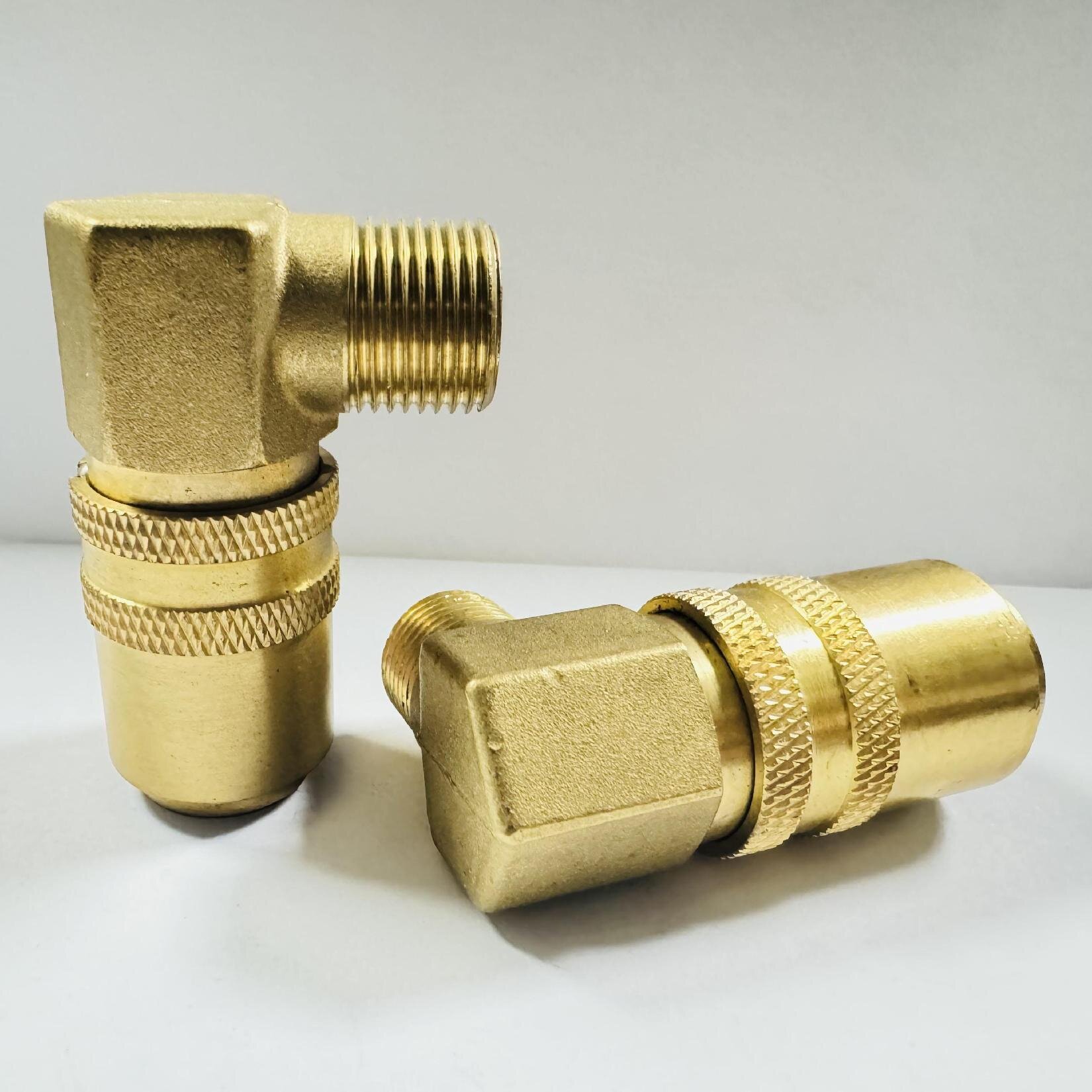
Attempting to mate a European plug with incompatible regional profiles introduces immediate physical dangers and severe leakage risks. For instance, the ARO profile dominates the US market and features a distinctly longer nose. The Japanese Nitto profile includes a unique step-down geometry on the probe. Forcing a European plug into an ARO or Nitto socket might temporarily engage the locking sleeve. However, the internal O-ring will not seat correctly against the plug head.
Common Mistake: Relying on a "click" sound as proof of compatibility. A mismatched connection creates an unstable mechanical lock. Under standard industrial pressures (often 90 to 120 PSI), the connection becomes a severe projectile hazard. The plug can forcefully eject, potentially injuring personnel and damaging nearby machinery.
Maintenance teams need a standardized framework to identify existing plant profiles accurately. Relying on visual inspection alone leads to errors. Equip your technicians with digital calipers and follow a strict diagnostic sequence to verify compatibility.
Measure the Plug Head Outer Diameter: Place the caliper jaws across the widest flat portion of the plug tip. European DN 7.2 profiles will consistently measure right around 7.2mm.
Measure the Locking Groove Width: Determine the distance between the top and bottom edges of the recessed groove. This dictates whether the socket's locking balls can properly seat.
Measure the Nose Length: Measure from the very tip of the plug down to the start of the locking groove. This depth must perfectly match the internal valve placement of the socket.
Establishing strict criteria for cross-brand interchangeability prevents system failures. Many reputable brands offer interchange series designed to safely mimic the European profile. When utilizing cross-brand interchange parts, always consult a standardized compatibility matrix.
Profile Designation | Regional Origin | Typical Plug Outer Diameter | Cross-Mating Compatibility with Euro DN 7.2 |
|---|---|---|---|
European Standard (DN 7.2) | Europe | 7.2mm | Native |
ISO 6150 B (Industrial) | International / US | Varies (Distinct step) | Incompatible (Severe Leak Risk) |
Nitto Kohki (Hi-Cupla) | Japan / Asia | Extended probe style | Incompatible (Projectile Hazard) |
ARO 210 | North America | Long nose | Incompatible (Mechanical Failure) |
Operational limits directly depend on the coupling's internal valve configuration and seal material. You must evaluate the system pressure and ambient temperature before selection. Standard single shut-off couplings place a check valve solely in the socket. They work perfectly for general compressed air circuits. Upon disconnection, the air on the plug side exhausts rapidly into the atmosphere.
Double shut-off designs feature valves in both the plug and socket. They prevent fluid spillage from both ends upon disconnection, making them mandatory for chemical or water lines. Dry disconnect variants take this further by utilizing flush-face valves. They ensure virtually zero fluid loss and prevent air inclusion during connection, ideal for sensitive hydraulic environments.
Specifying the correct connection end is vital for a leak-free static seal at the manifold or tool inlet. Differentiate carefully between parallel and tapered threads. Parallel threads, such as BSPP (British Standard Pipe Parallel), require a bonded seal, O-ring, or copper washer to create a pressure-tight barrier. Tapered threads, like NPT (National Pipe Tapered), rely on thread deformation and PTFE tape to seal.
Best Practice: When dealing with European machinery, specify a metric thread coupling to ensure perfect alignment with factory-installed manifolds. Metric connections utilize a parallel thread geometry and rely on an integrated sealing ring at the base of the thread. Forcing a mismatched thread type strips the metal and guarantees constant air leakage.
Match the coupling's flow coefficient (Cv value) to the specific CFM (Cubic Feet per Minute) requirements of your pneumatic tool. The Cv value quantifies the volume of fluid or air that can pass through the coupling at a specific pressure drop. If you install a restrictive coupling with a low Cv value on a high-demand impact wrench, you cause severe tool starvation.
Tool starvation manifests as sluggish performance and reduced torque output. To prevent this, calculate the peak CFM demand of the application. Select a coupling that exceeds this requirement while maintaining an acceptable pressure drop threshold, typically kept below 5 PSI across the connection.
General compressed air systems rely heavily on standard brass and steel constructions. Steel couplings offer superior mechanical strength and resist damage from accidental drops on factory floors. However, untreated steel corrodes quickly if the air compressor introduces high moisture levels into the lines. Brass provides an excellent alternative. It naturally resists rust and corrosion, making it a reliable choice for humid environments or systems lacking advanced air dryers.
For flexible routing to hand tools, integrate a brass hose barb nipple. This configuration allows you to connect low-pressure rubber or polyurethane hoses directly to the coupling. Secure the hose over the barb with a high-quality crimped ferrule or an ear clamp to ensure it withstands continuous dynamic movement without blowing off.
Injection molding facilities present extreme thermal and chemical challenges. Standard pneumatic connectors will melt or fail catastrophically in these environments. You must specify a dedicated mold water coupling designed expressly for thermal regulation circuits.
Temperature-resistant seals are mandatory. Standard NBR (Nitrile) O-rings degrade rapidly when exposed to hot water or thermal transfer oils above 100°C. You must upgrade to Viton (FKM) seals, which reliably withstand operating temperatures up to 200°C without hardening, swelling, or losing their elastomeric properties. Furthermore, mold cooling components typically utilize brass or stainless steel to prevent rust buildup from restricting internal water channels.
Many specialized industrial sectors rely on proprietary or legacy standardizations. In plastics manufacturing, facilities often build their entire tooling ecosystem around specific cooling line profiles. For example, verifying compatibility becomes critical when a plant historically relies on a HASCO quick coupling standard. These specific profiles feature distinct internal flow paths optimized strictly for liquid cooling.
You cannot mix general pneumatic European profiles with liquid-optimized mold profiles. Their locking sleeves and valve poppets are engineered for completely different fluid dynamics. Integrating the wrong standard into an established industry-specific ecosystem disrupts thermal regulation and risks sudden fluid leaks during active production cycles.
Seal failure stands as the most common reason quick couplings leak. NBR seals handle standard compressed air well, but they react poorly to incompatible fluids. Modern rotary screw air compressors often utilize synthetic lubricating oils. These synthetic oils travel downstream in aerosol form and attack standard NBR O-rings aggressively.
The chemical reaction causes the NBR material to swell, soften, and eventually fragment. Extreme thermal cycling further accelerates this degradation. As the seal hardens from repeated temperature spikes, it loses its ability to rebound and fill the microscopic gaps between the plug and socket. Upgrading to specialized elastomers like FKM or EPDM mitigates this risk entirely.
Industrial environments subjects connections to relentless physical abuse. Mechanical wear from high-frequency vibration significantly impacts the locking sleeve and internal ball bearings. When attached directly to heavy percussive tools like impact wrenches or chipping hammers, the constant vibration chatters the connection.
This chattering action gradually wears down the hardened steel balls and carves physical indents into the plug groove (a process known as brinelling). Over time, the tolerance gap widens. The locking sleeve loses tension, increasing the risk of an accidental disconnection while the line remains fully pressurized. Utilizing heavy-duty steel plugs and introducing short whip hoses between the tool and the coupling significantly reduces direct vibration transfer.
Procuring unverified, low-tolerance knockoff couplings creates a cascade of hidden operational inefficiencies. Off-brand interchange parts rarely adhere to the strict geometric tolerances required by the original European standard. The plug might engage the socket, but microscopic gaps remain around the primary sealing surfaces.
These misalignments generate continuous micro-leaks throughout the entire facility. Because these leaks are often too small to hear over ambient factory noise, they remain undetected for months. Consequently, air compressors must run continuously to maintain baseline system pressure. This forced overworking drastically shortens compressor lifespans and drives up daily energy expenditures to unsustainable levels.
Selecting the correct European standard connection ensures your fluid and pneumatic systems run safely and efficiently. By rigorously evaluating profile geometry, thread types, and material composition, you prevent the severe operational disruptions caused by mismatched components.
Follow Shortlisting Logic: Always verify the plug profile first. Next, determine flow and pressure requirements. Then, select the appropriate material and seal based on the fluid. Finally, specify the correct connection thread to match your manifold.
Implement Strict Diagnostics: Audit your current plant connections using digital calipers to measure plug head diameter and groove width accurately.
Prioritize Verified Data: Consult with technical suppliers who provide verifiable flow charts and exact interchange data before committing to bulk component upgrades.
A: No. Despite similar functions, the plug geometry differs significantly. Forcing a connection will result in damaged O-rings, severe leakage, or a projectile hazard under pressure.
A: Measure the plug head diameter and the shape of the locking groove. European profiles typically feature a wider, flatter head (e.g., 7.2mm), whereas Japanese (Nitto style) profiles have a distinct, longer probe-like geometry.
A: Not necessarily. The system's maximum pressure rating is dictated by its weakest component. While the coupling may be rated for 35 bar, a standard hose barb connection secured with a worm-gear clamp will fail at a much lower threshold.
A: No. While both originated in Europe, HASCO profiles are specifically engineered for mold cooling applications with distinct locking mechanisms and flow paths optimized for liquids, whereas standard Euro pneumatic profiles are optimized for compressed air.


